Genbox
Uniformly Distributed Mesh
Suppose you wish to simulate flow through an axisymmetric pipe,
of radius \(R=0.5\) and length \(L=4\). You estimate that you will
need 3 elements in radial \((y)\) direction, and 5 in the \(x\) direction,
as depicted in Fig. 7.
This would be specified by the following input file (called pipe.box)
to genbox:
axisymmetric.rea
2                      spatial dimension
1                      number of fields
#
#    comments:   This is the box immediately behind the
#                refined cylinder in Ugo's cyl+b.l. run.
#
#
#========================================================
#
Box 1                         Pipe
-5 -3                         Nelx  Nely
0.0   4.0   1.0               x0  x1   ratio
0.0   0.5   1.0               y0  y1   ratio
v  ,O  ,A  ,W  ,   ,          BC's:  (cbx0, cbx1, cby0, cby1, cbz0, cbz1)
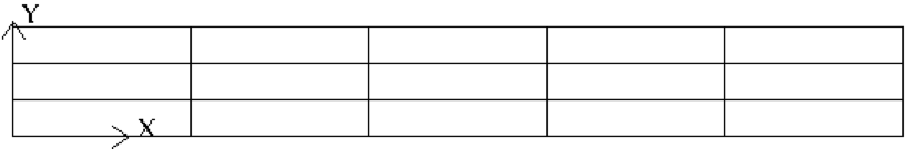
Fig. 7 Axisymmetric pipe mesh.
The first line of this file supplies the name of an existing 2D
.reafile that has the appropriate run parameters (viscosity, timestep size, etc.). These parameters can be modified later, but it is important thataxisymmetric.reabe a 2D file, and not a 3D file.The second line indicates the number of fields for this simulation, in this case, just 1, corresponding to the velocity field (i.e., no heat transfer).
The next set of lines just shows how one can place comments into a
genboxinput file.The line that starts with “Box” indicates that a new box is starting, and that the following lines describe a typical box input. Other possible key characters (the first character of Box, “B”) are “C” and “M”, more on those later.
The first line after “Box” specifies the number of elements in the \(x\) and \(y\) directions. The fact that these values are negative indicates that you want
genboxto automatically generate the element distribution along each axis, rather than providing it by hand. (More on this below.)The next line specifies the distribution of the 5 elements in the \(x\) direction. The mesh starts at \(x=0\) and ends at \(x=4.0\). The
ratioindicates the relative size of each element, progressing from left to right.The next line specifies the distribution of the 3 elements in the \(y\) direction, starting at \(y=0\) and going to \(y=0.5\). Again,
ratio=1.0 indicates that the elements will be of uniform height.The last line specifies boundary conditions on each of the 4 sides of the box:
- Lower-case v indicates that the left \((x)\) boundary is to be a velocity
boundary condition, with a user-specified distribution determined by
routine
userbcin the.usrfile. (Upper-case \(V\) would indicate that the velocity is constant, with values specified in the .rea file.) - O indicates that the right \((x)\) boundary is an outflow boundary – the flow leaves the domain at the left and the default exit pressure is \(p=0\).
- A indicates that the lower \((y)\) boundary is the axis—this condition is mandatory for the axisymmetric case, given the fact that the lower domain boundary is at \(y=0\), which corresponds to \(r=0\).
- W indicates that the upper \((y)\) boundary is a wall. This would be equivalent to a v or V boundary condition, with \({\bf u}=0\).
Other available boundary conditions are given in Boundary Conditions.
- Lower-case v indicates that the left \((x)\) boundary is to be a velocity
boundary condition, with a user-specified distribution determined by
routine
Graded Mesh
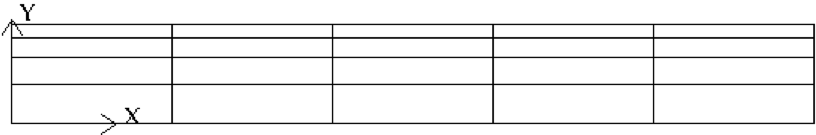
Fig. 8 Axisymmetric pipe mesh, graded
Suppose you wish to have the mesh be graded,
that you have increased resolution near the wall.
In this case you change ratio in the \(y\)-specification
of the element distribution. For example, changing the 3 lines
in the above genbox input file from
-5 -3                         Nelx  Nely
0.0   4.0   1.0               x0  x1   ratio
0.0   0.5   1.0               y0  y1   ratio
to
-5 -4                         Nelx  Nely
0.0   4.0   1.0               x0  x1   ratio
0.0   0.5   0.7               y0  y1   ratio
yields the mesh shown in Fig. 8.
User-Specified Distribution
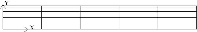
Fig. 9 Axisymmetric pipe mesh, user specified.
You can also specify your own, precise, distribution of element
locations. For example, another graded mesh similar to the
one of the preceding example could be built by changing the
genbox input file to contain:
-5  4                                               Nelx  Nely
0.0   4.0   1.0                                     x0  x1   ratio
0.000    0.250    0.375    0.450    0.500           y0  y1 ... y4
Here, the positive number of elements for the \(y\) direction indicates
that genbox is expecting Nely+1 values of \(y\) positions on the
\(y\)-element distribution line. This is the genbox default, which
explains why it corresponds to Nely \(>\) 0. The corresponding mesh
is shown in Fig. 9.